
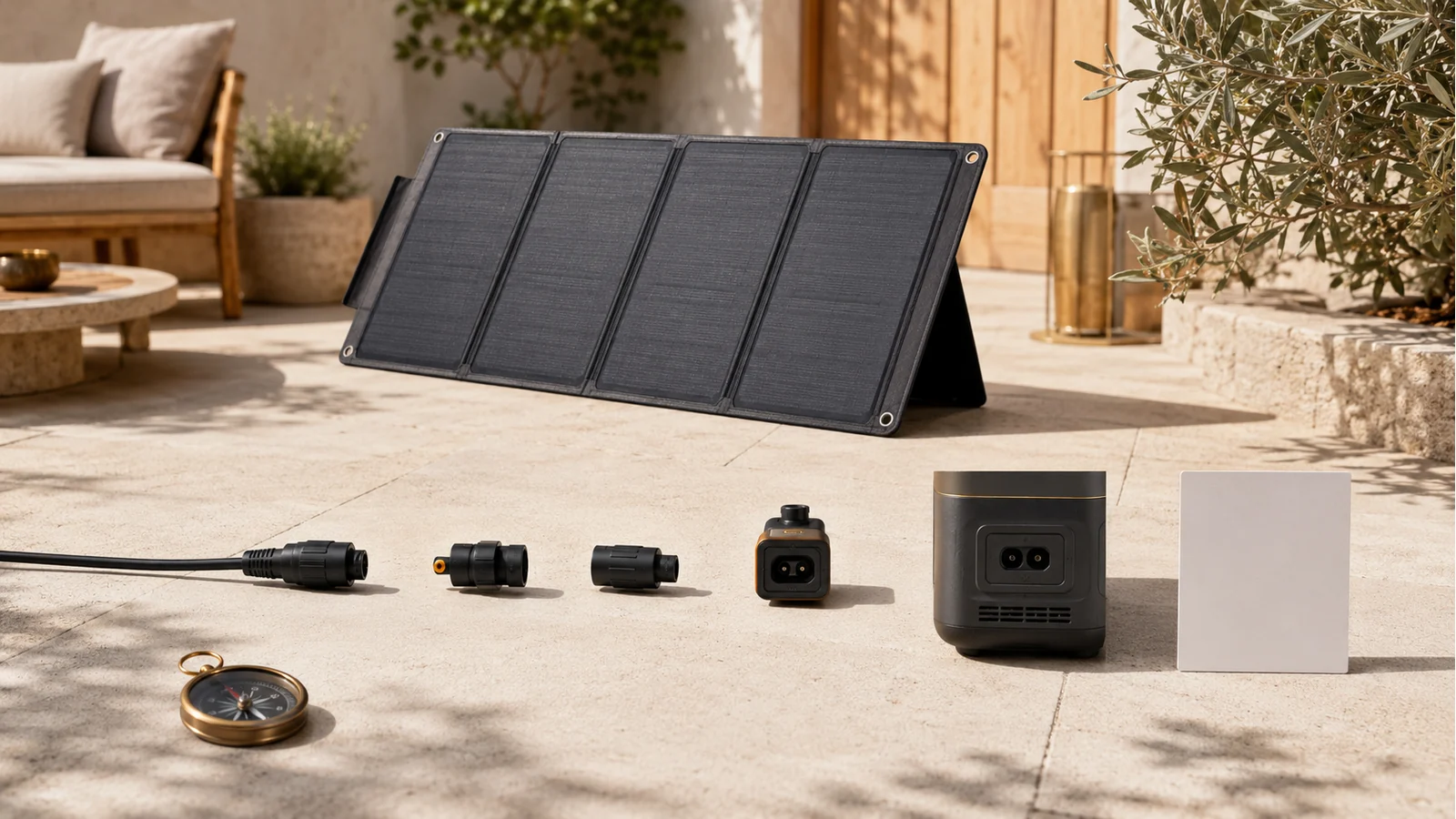
Evidence summary: This research-based buyer guide explains how to screen a portable solar panel for charging an exact portable power station. It uses current U.S. government, national-laboratory, safety-certification, and manufacturer sources checked on July 22, 2026. No panel or power station was purchased, measured, tested, ranked, or recommended. No affiliate relationship, price research, charge-time model, installation instruction, or household-wiring claim applies.
Evidence checked: July 22, 2026
Manufacturer specifications checked: July 22, 2026
Hands-on testing: Not performed
Interactive charge-time calculation: Not included
Quick answer
Start with the exact power-station input specification, not the panel’s advertised wattage. A panel remains only a candidate when all of these are known and acceptable:
- the exact station model, market version, current manual, and solar-input port;
- the station’s minimum and maximum input voltage, maximum input current, maximum input power, charging-temperature range, and allowed panel configuration;
- the panel’s rated power, open-circuit voltage (
Voc), voltage at maximum power (Vmp), short-circuit current (Isc), current at maximum power (Imp), connector, cable, polarity, operating range, size, weight, and weather limits; - the exact cable or manufacturer-approved adapter path;
- a temporary placement that is permitted, stable, unshaded enough to be useful, protected against unsafe weather, and reachable without routing cables through exits or creating trip hazards;
- a cold-condition voltage review when the panel or multi-panel arrangement could approach the station’s maximum input voltage.
Rated watts alone do not prove compatibility, charging speed, or real-world output. A connector that appears to fit does not resolve voltage, current, polarity, adapter, weather, or configuration limits.
Safety constraint: Stop when the manuals, connector path, polarity, voltage window, multi-panel instructions, weather boundary, charging temperature, battery condition, placement permission, or cable route is unresolved. Do not improvise adapters, series/parallel wiring, balcony mounting, household-outlet connection, or backfeeding.
Who this guide is for
This guide is for U.S. renters, apartment dwellers, and small-home households that already completed the renter-readiness, claims-literacy, safety, product-family, and static-sizing decisions.
It helps answer:
Which portable panel form factor and specification set may fit my exact power station and temporary charging location?
It does not answer:
- how long a panel will take to recharge a station;
- which panel or brand is best;
- whether a landlord, building, fire authority, electrical authority, or local rule permits a particular placement;
- how to wire panels in series or parallel;
- how to install a fixed, railing-mounted, rooftop, plug-in, or grid-connected solar system;
- whether a solar setup can support a medical device or a whole-home circuit;
- whether a named panel will produce its rated wattage in the reader’s weather.
Stop before shopping if any foundation is missing
Pause the panel decision when:
- the household has not completed the outage-readiness preflight;
- the power-station category or exact station family is still unresolved;
- the required delivered energy, simultaneous continuous output, or startup event is unknown;
- the station has not passed the applicable battery-condition, recall, charging, storage, and backfeeding checks;
- the exact station manual or panel manual cannot be found;
- the proposed use would connect generation to household wiring, an outlet, a transfer device, or a building electrical system;
- the only feasible placement depends on unapproved balcony, railing, roof, façade, common-area, or permanent mounting;
- the panel would block an exit, walkway, fire-safety feature, or shared access route;
- the station would have to remain in rain, standing water, direct weather exposure, or outside its charging-temperature range;
- damaged, wet, swollen, unusually hot, leaking, discolored, misshapen, noisy, or odorous equipment is present.
A stopped decision is a valid result. It means a no-solar route or a separate qualified project is more appropriate than guessing.
Start with the power station, not the panel
Record the station’s exact model and market version. Similar product names can have different ports, voltage ranges, input limits, accessories, or regional specifications.
From the current manual, capture:
| Station field | Why it matters |
|---|---|
| Solar/DC input port | Identifies the actual connection point |
| Minimum working/input voltage | A panel may not operate the charging controller below this value |
| Maximum input voltage | Exceeding it can fall outside the approved input boundary |
| Maximum input current | Current handling is model- and port-specific |
| Maximum input power | A higher panel nameplate does not force the station to accept more power |
| Number of solar inputs | Separate ports can have separate limits |
| Approved adapters/cables | Mechanical fit is not enough |
| Allowed panel arrangements | Multi-panel use must follow the exact manual or connection guide |
| Charging-temperature range | The station may prohibit charging in conditions where the panel can still produce |
| Weather/water limits | A panel rating does not transfer to the station |
Do not infer these fields from a retailer title, a bundle name, an image of a connector, or another model in the same product line.
Read the five panel electrical fields separately
Rated power (Pmax)
Rated power is a test-condition result, not a promise of continuous field output. The U.S. Department of Energy explains that photovoltaic ratings are measured under standard conditions, while real sunlight intensity, cell temperature, time, season, angle, clouds, and other losses differ in practice.
Open-circuit voltage (Voc)
Voc is the panel voltage with no load connected. It is not interchangeable with working voltage. Compare it—and any required cold-condition adjustment or manufacturer configuration rule—with the station’s maximum input-voltage boundary.
Voltage at maximum power (Vmp)
Vmp is the operating voltage associated with the panel’s maximum-power point under its stated test conditions. It helps determine whether the panel’s operating voltage sits inside the station’s accepted input window.
Short-circuit current (Isc)
Isc is a test value used for electrical characterization and protection decisions. It is not the same as the panel’s normal maximum-power current, and it does not by itself tell you how the station will limit or accept current.
Current at maximum power (Imp)
Imp is the current at the maximum-power point under the stated test conditions. Compare the exact current and power fields using the station manual or manufacturer connection guide. Do not assume that an apparent overage is automatically safe clipping—or automatically incompatible—without an exact documented disposition.
Why rated watts do not decide compatibility
A "200 W" label leaves several questions unanswered:
- Is the panel
Vocbelow the station’s maximum input voltage in the expected conditions? - Is
Vmpinside the accepted operating window? - Are
IscandImphandled by the exact input and connection method? - Is the panel using the exact connector, cable, polarity, and adapter the station expects?
- Does the station accept one panel, multiple panels, or only named arrangements?
- Is the station’s maximum solar power lower than the combined panel rating?
- Is charging allowed at the expected station temperature?
- Will the temporary site provide enough direct light and safe cable routing to make deployment useful?
A station may limit accepted power, but this guide does not publish a universal clipping rule. The exact manual controls.
Standard test conditions are not your balcony, yard, or window
DOE describes PV module ratings at standard test conditions of 1,000 W/m² irradiance and 25°C cell temperature. In practice, sunlight intensity is usually lower and module temperature is often higher. DOE also notes that solar resource varies with time of day, season, angle, and clouds. NREL’s PVWatts model treats shading, soiling, snow, mismatch, wiring, connections, nameplate rating, age, and availability as separate loss inputs.
That means:
- a rated panel wattage is not a charging-speed guarantee;
- output through glass, under shade, or at a poor angle may be materially lower;
- moving clouds can change output rapidly;
- hot cells generally lose voltage;
- colder conditions can increase voltage relative to hotter operation, so a close-to-limit configuration needs a documented cold-condition review;
- a bifacial rear-side claim depends on rear irradiance and setup conditions rather than existing automatically.
This guide does not estimate recharge time. After exact compatibility and temporary-site conditions are resolved, the solar recharge time calculator can model the explicit energy and accepted-power ranges you enter. It does not forecast weather, establish compatibility, or guarantee a completion time.
Connector, cable, adapter, and polarity are one compatibility path
UL Solutions evaluates photovoltaic connectors under UL 6703 and UL 6703A as specific components. This supports treating the connector path as an exact equipment combination, not a generic visual category.
Before shortlisting, confirm:
- the panel’s output connector;
- the station’s input connector;
- every extension cable and adapter in between;
- polarity;
- connector and cable current/voltage ratings;
- whether the adapter is supplied, named, or approved for the exact station and panel;
- whether the connection guide permits the arrangement.
Terms such as "MC4," "photovoltaic connector," "8 mm," "XT60," or "XT60i" do not erase model-specific requirements. Do not cut, splice, reverse, force, or improvise a connector to make a panel fit.
Do not improvise multiple-panel wiring
Combining panels changes the electrical arrangement. This guide does not teach series or parallel wiring and does not calculate a multi-panel string.
Use multiple panels only when the exact station manual or manufacturer connection guide identifies:
- the permitted panel count;
- the connection accessory;
- the arrangement;
- the resulting voltage/current boundary;
- the port allocation;
- the environmental and cable requirements.
If the documentation is unclear, retain one documented panel candidate or stop.
Check cold-condition voltage before approaching the maximum
DOE explains that higher solar-cell temperature tends to reduce voltage. Panel specifications may also publish a negative voltage temperature coefficient. The practical decision is not to invent a universal correction factor; it is to require an exact documented review when Voc or a manufacturer-approved multi-panel arrangement approaches the station’s maximum input voltage in expected cold conditions.
This release does not calculate cold-corrected voltage. A missing review is a hold, not a reason to assume the nameplate value will remain unchanged.
Check physical fit before electrical fit
Portable panels can be long, heavy, awkward, and wind-sensitive when unfolded. Record:
- folded and unfolded dimensions;
- weight;
- stand or support method;
- cable length and bend/routing constraints;
- setup and pack-down time;
- storage location;
- the route between storage and deployment;
- whether the panel can remain stable without attaching it to a railing, façade, roof, or shared structure;
- whether the placement creates a trip, fall, egress, or falling-object hazard;
- whether theft or unattended exposure makes the plan impractical.
A panel that is electrically compatible but cannot be deployed or stored safely is not a fit.
Weather and water ratings must be component-specific
A panel’s published ingress-protection or water-resistance claim applies only to the exact product and stated conditions. It does not automatically cover:
- the power station;
- open connector ends;
- an adapter;
- an extension cable;
- a damaged seal;
- immersion, heavy rain, long-term damp storage, or wind loading;
- charging outside the station’s temperature range.
For example, Jackery currently lists the SolarSaga 200W as IP68 while warning against heavy rain or submersion. BLUETTI currently states that the AC180 power station is not waterproof and lists a 32°F–104°F charging range. The limiting component controls the setup.
Do not leave a power station outdoors merely because the panel has a higher weather rating.
Keep portable charging separate from plug-in or fixed solar
A portable panel charging a self-contained power station is not the same project as:
- connecting a solar product to a household outlet;
- exporting power into premises wiring;
- installing a balcony plug-in solar system;
- attaching modules to a railing, roof, façade, or building structure;
- using a transfer device, panel connection, or other home-integration equipment.
UL Solutions launched a separate U.S. certification framework for plug-in solar systems in January 2026, reflecting the different system-level safety questions. CPSC separately warns that male-to-male cords and residential backfeeding can cause electrocution and fire.
If the proposal touches household wiring or permanent mounting, stop C07 and use the property, local-authority, product-system, and qualified-professional route.
Exact current examples show why the worksheet matters
The following manufacturer specifications are examples only. They are not independent performance evidence or recommendations.
EcoFlow example
EcoFlow currently lists DELTA 2 Max solar input as 11–60 V, 15 A, and 500 W on one port, with two ports supporting a stated 1,000 W total. Its NextGen 220W bifacial portable panel is listed at 220 W front-side rated power, 21.5 V Voc, 18.4 V Vmp, 12.4 A front-side Isc, 11.9 A front-side Imp, photovoltaic connectors, and IP68.
The useful lesson is not that the pair is best. It is that station input limits and panel electrical fields are separate records, and the exact cable/port arrangement still matters.
Jackery example
Jackery currently lists two DC 8 mm inputs on the Explorer 1000 v2, with different current limits across 12–16 V and 16–60 V working-voltage ranges and a stated 400 W combined maximum. The current SolarSaga 200W page lists 200 W at STC, 22 V Voc, 18 V Vmp, 12.5 A Isc, 11.5 A Imp, a 60 V maximum system voltage, IP68, and an unfolded length of roughly 90 inches.
The useful lesson is to use the exact connection guide. A single wattage or connector label does not resolve the station’s two voltage ranges, port allocation, current limits, or physical deployment.
BLUETTI example
BLUETTI currently lists AC180 solar input as 500 W maximum, 12–60 VDC Voc, and 10 A, and its FAQ calls for total open-circuit voltage within 12–60 V, no more than 500 W, and MC4 connectors. The same page states that the station is not waterproof and lists charging at 32°F–104°F.
The useful lesson is that electrical compatibility and environmental suitability must both pass.
Shortlist worksheet
Complete this before comparing price or brand.
| Field | Record |
|---|---|
| Exact station model and market | |
| Current station manual URL/date | |
| Solar-input port | |
| Minimum input voltage | |
| Maximum input voltage | |
| Maximum input current | |
| Maximum input power | |
| Approved cable/adapter | |
| Exact panel model | |
| Current panel manual URL/date | |
Pmax |
|
Voc |
|
Vmp |
|
Isc |
|
Imp |
|
| Connector and polarity | |
| Cold-condition voltage review | |
| Multi-panel status | single documented panel / manufacturer-approved arrangement / hold |
| Folded dimensions and weight | |
| Unfolded dimensions | |
| Temporary placement permission | |
| Cable route and egress check | |
| Wind/stability plan | |
| Panel weather limit | |
| Station weather limit | |
| Station charging-temperature status | |
| Storage and transport route | |
| Battery-condition/safety check | |
| Outcome | candidate / hold / no-solar route / separate solar project |
Decision outcomes
Candidate
Use this only when the exact single-panel or manufacturer-approved arrangement passes manuals, connector path, polarity, electrical window, cold-condition review, placement, weather, charging-temperature, and safety checks.
Hold
Use this when a fact is unknown, especially permission, manual revision, adapter, polarity, voltage, multi-panel arrangement, weather boundary, or cold-condition review.
No-solar route
Use this when there is no safe, permitted, stable, useful temporary placement or the station cannot be charged within its documented limits. AC charging before an outage, a different continuity plan, relocation, or another non-solar route may be more appropriate.
Separate solar project
Use this when the proposal involves fixed mounting, a building structure, household wiring, a plug-in solar system, export to premises wiring, or installation work.
What remains unknown
This guide does not establish:
- compatibility for every station, panel, adapter, or cable;
- a universal rule for allowable over-paneling, current clipping, or multi-panel wiring;
- cold-corrected voltage for any panel or location;
- actual wattage, daily energy, or recharge time in a reader’s site and weather;
- permission for a balcony, railing, roof, window, yard, common area, or lease;
- wind loading or structural suitability;
- lifecycle emissions, savings, payback, or environmental superiority;
- product quality, durability, warranty performance, or value;
- safe support for a medical device;
- a household-wiring or plug-in solar design.
These are deliberate boundaries, not missing recommendations.
Related decision handoffs
- Renter readiness: confirm that solar charging solves an approved outage need and that placement is permitted.
- Capacity and claim literacy: understand W, Wh, rated values, usable energy, and the limits of manufacturer runtime/charging claims.
- Portable-power safety: verify condition, recall, charger, cable, storage, temperature, and no-backfeeding boundaries.
- Product-family fit: select the station feature family before choosing an accessory ecosystem.
- Static sizing: define delivered Wh, continuous W, and startup events before deciding how much recharge input is useful.
- Solar recharge method: the solar recharge time calculator estimates active charging hours from explicit energy and accepted-power ranges after compatibility is resolved.
- Ecosystem compatibility: the Renogy ecosystem guide maps exact-component compatibility questions without approving a setup or predicting charging performance.
- Balcony or plug-in solar: any household-wiring or fixed-mounting route is a separate project, not a portable-panel shortcut.
Method and sources
This release uses a deterministic compatibility gate, not a performance model. It can return a documented candidate, hold, no-solar route, or separate-project route. It does not calculate energy production or charge time.
Key sources checked July 22, 2026:
- U.S. Department of Energy — Solar Photovoltaic Performance and Efficiency Basics
- U.S. Department of Energy/FEMP — Optimizing Solar Photovoltaic Performance for Longevity
- NREL — PVWatts Calculator
- UL Solutions — Solar Materials and Components Certification
- UL Solutions — U.S. Plug-In Solar Certification Framework
- U.S. CPSC — Male-to-Male Extension Cord and Backfeeding Warning
- U.S. Fire Administration — Battery Fire Safety
- EcoFlow — DELTA 2 Max current specifications
- EcoFlow — NextGen 220W Bifacial Portable Solar Panel specifications
- Jackery — Explorer 1000 v2 current specifications
- Jackery — SolarSaga 200W current specifications
- BLUETTI — AC180 current specifications and FAQ
Recheck every material source and manual before public deployment and again before any indexable release.